Principle of Screw Compressor and Analysis of Common Faults
working principle
Basic structure 2
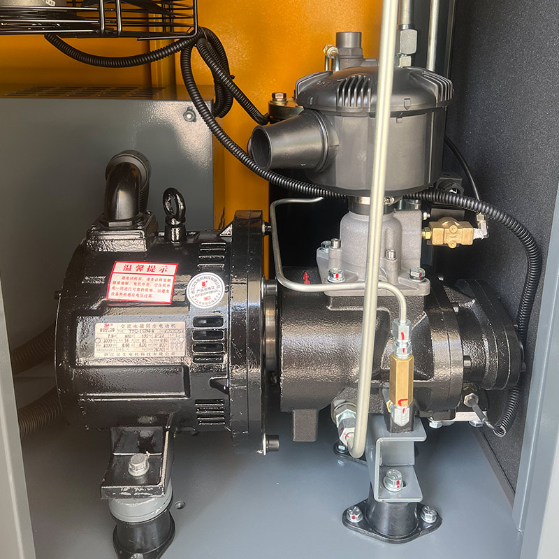
main parts
The main parameters
main category
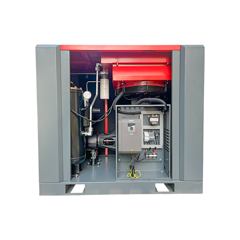
compressor unit
single screw compressor
Common fault analysis
Repair and Maintenance
working principle
Relying on the pair of male and female rotors that are meshing and moving, the volume between the pair of “V”-shaped teeth formed by their teeth, tooth grooves and the inner wall of the casing changes periodically to complete the refrigerant gas suction-compression-discharge working process
Working process of screw compressor
Features of screw compressors
1) Working in the range of medium cooling capacity, less wearing parts, which is conducive to the realization of operation automation, high reliability and efficiency; 2) high processing precision, high price, and large noise; 3) high efficiency of partial load, No piston-type hydraulic shock and centrifugal surge phenomenon:
4) With the oil injection method, a large amount of oil needs to be injected and corresponding auxiliary equipment must be equipped.
Screw compressor application industry
Screw air compressors have been widely used in the current industrial and mining industries, mainly in machinery, metallurgy, power generation, automobile shipbuilding, textiles, chemicals, petrochemicals, electronics, papermaking, food and other industries.
Advantages of open compressors
(1) The compressor is separated from the motor, so that the compressor can be used in a wider range
2) The same compressor can adapt to different refrigerants. In addition to using halogenated hydrocarbon refrigerants, ammonia can also be used as refrigerant by changing the materials of some parts. (3) According to different refrigerants and operating conditions , equipped with motors of different capacities.
Development Trends and Research Results
The internal volume ratio adjustment mechanism is generally used; (1
(2) Single-machine two-stage compression is adopted;
(3) Start the miniaturization of screw compressors.
Semi-hermetic screw compressor
Features:
(1) Both male and female rotors of the compressor adopt 6:5 or 7:5 teeth
(2) The oil separator is integrated with the main engine
(3) The built-in motor is cooled by refrigerant gas (4) Pressure differential oil supply
(5) Oil-free cooling system
Reason for adoption:
When the working conditions of the air-cooled and heat pump units are relatively bad, the temperature of the exhaust gas and lubricating oil or the temperature of the built-in motor will be too high when the condensing pressure is high and the evaporation pressure is low, which will cause the protection device to operate and the compressor to stop. In order to ensure the performance of the compressor It operates within the working limit and can be cooled by spraying liquid refrigerant.
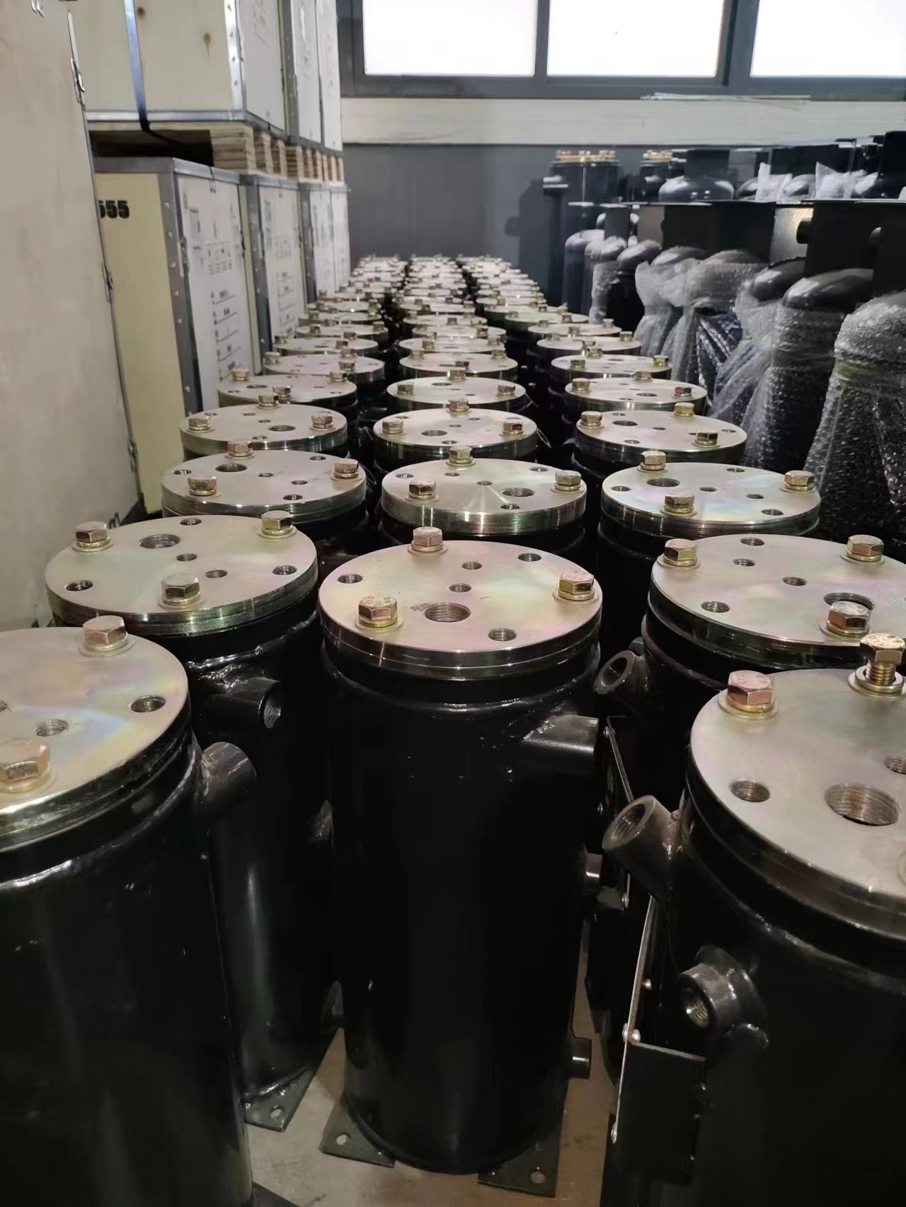
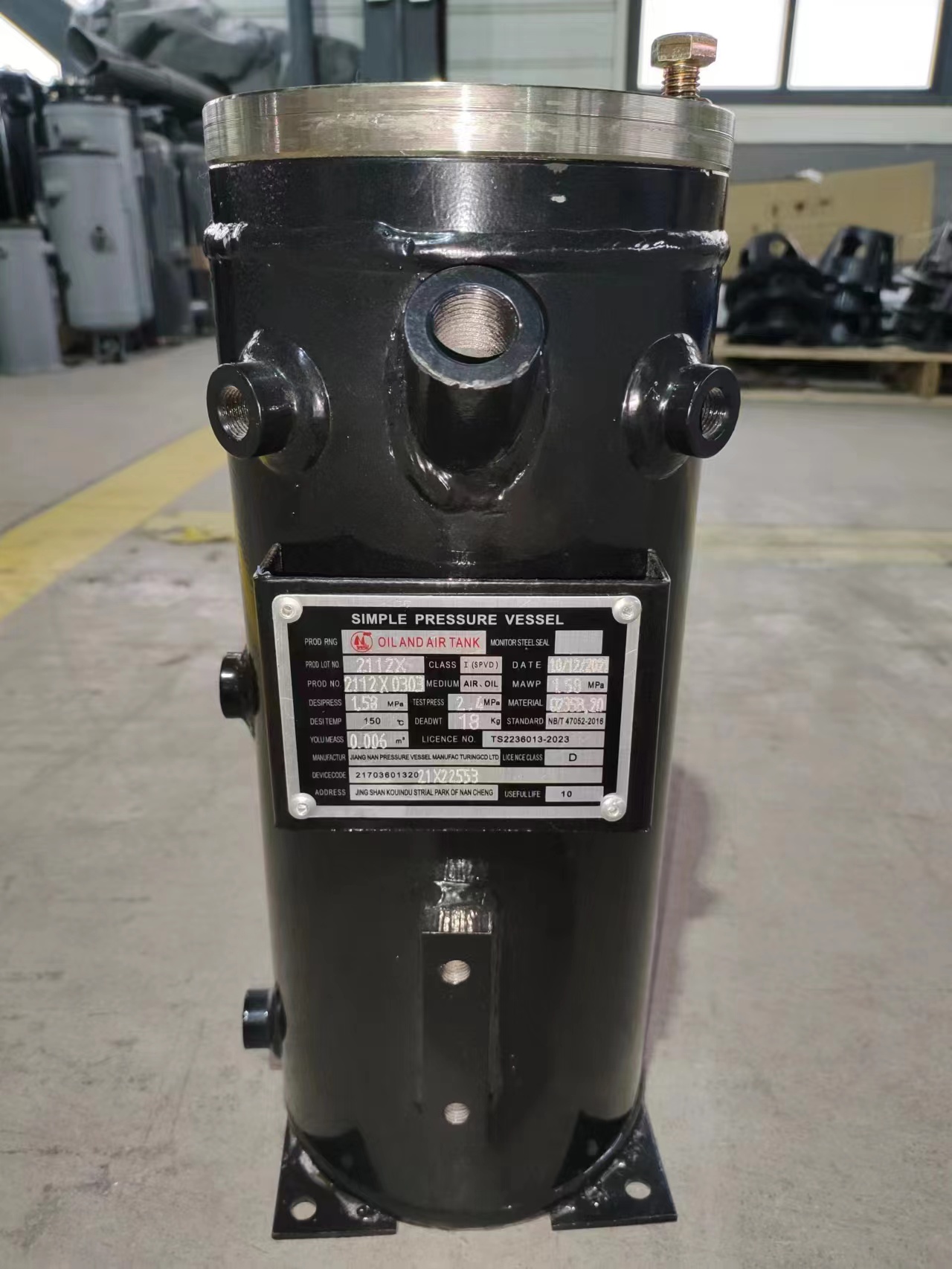
several oil separators
a) Horizontal oil separator b) Vertical oil separator c) Secondary oil separator
Screw compressor auxiliary system 6.2
Air Filtration System Introduction
The intake filter is the most important filter in the compressor
Dust is the biggest cause of engine wear and can significantly reduce the life of compressor elements, oil separators and compressor oil
The biggest task of a dry air filter is to ensure that engine and compressor components have adequate protection against wear and tear under all foreseeable dust conditions.
By blocking the ingress of contaminants through air intake filters, we can extend the life of:
Diesel engines
compressor components
oil separator
compressor oil filter
compressor oil
Bearings and other moving components
Screw compressor auxiliary system
Oil Separator System Introduction
The Importance of Compressor Oil Separation Systems
Compressor oil, which is mainly used to dissipate the heat generated during compression, needs to be separated from the air again. Any lubricating oil mixed in the compressed air will lead to increased oil contamination and cause overloading of the compressed air network, condenser and condensing process
A high oil residue will increase the consumption of lubricating oil and the overall operating cost, and obtain low-quality compressed air.
Less oil residue also means less oil entering the condensate drain, which is also good for the environment
The lubricating oil is first separated from the air from the air receiver with very high efficiency by a centrifugal separator. The lubricating oil will fall to the bottom of the receiver due to gravity.
Screw compressor auxiliary system
Measures to ensure long service life of oil separator
Accumulated dust, old oil product, air contamination or wear can reduce the life of the oil separator.
In order to ensure the best service life of the oil separator, the following measures must be taken.
In general, the accumulation of solid particles in the fine separation layer will lead to an increase in pressure difference, thereby reducing the service life of the oil separator
A
Dust entering the compressor oil can be limited by timely replacement of air and oil filters and by observing oil change times.
Choosing the right oil is also very important. Only use approved, anti-aging and water-resistant oils.
Using an unsuitable oil that lacks sufficient antioxidant capacity, even for a short period of time, can cause the oil to become jelly-like in density and clog the oil separator due to the buildup of sediment.
Accelerated oil aging is caused by high operating temperatures. Therefore, sufficient attention must be paid to providing sufficient cold air and removing debris from the cooler in time.
When performing an oil change, all used oil must be drained to prevent damage from residual oil and incompatibility of the two oils.
Screw compressor auxiliary system
Oil Filtration System Introduction
The task of the oil filter is to remove all wear-causing impurities from the machine oil, but at the same time without separating the added special additives.
Dust and impurities in the compressor oil will accumulate between the casing of the compressor element and the rotating shaft, which will cause the rotating shaft to be damaged and the performance of the compressor to decline.
Compressor oil is also used to lubricate the bearings of the compressor elements, so dirt and impurities can also damage the bearing rollers. Compressor wear increases shaft contact and results in reduced compressor performance and shortened life of compressor components
Further damage to the bearing rollers can cause rupture of the casing and complete destruction of the compressor element.
Analysis of common faults Rotor exhaust temperature is too high
Possible causes and solutions
1. The cooling of the unit is not good and the oil supply temperature is high
1.1 Poor ventilation (installation site & hot air place)
1.2 Cooler heat exchange is poor (clean)
1.3 Oil circuit problem (thermostatic valve)
2. The oil supply is too small
2.1 Less oil storage (addition or replacement)
2.2 card()
2.3 Oil filter clogging (replacement)
2.4 The flow rate of oil is slow (ambient temperature)
Analysis of common faults After the air compressor starts running,
Possible causes and solutions 1. Electromagnetic failure or failure
1. Check whether it has been repaired or replaced by electricity
2. The intake valve cannot be opened (the valve is stuck tightly)
envelope
2Repair valve parts or replace seals
3 Control of tracheal leaks
3 Replace the control tube
4 min pressure min air leak
4 overhaul
Common fault analysis
Air compressor does not unload the safety valve trip
Possible causes and solutions 0
1 Solenoid valve out of control
1 repair or replace 0
2 The air intake is not closed
2 overhaul
3. Computer failure
3 Replace the computer
When the unit is running under load, no condensate is discharged
Possible causes and solutions
Drain hose clogged 1
Water delivery function
Overhaul and repair
If it is an electronic water delivery valve, it may be a circuit failure.
barrier
Excessive oil coming out of air filter after shutdown
· Possible causes and solutions
1. Check valve leakage
1. Repair and repair damaged parts
2 oil stop stuck
2Repair, cleaning and replacement of damaged parts
3. The air intake is not dead
3 Maintenance of intake valve

